- Have any questions?
- +86 15953537010
- admin@wepower-electronic.com
Selecting a high-quality device is only one aspect in getting accurate readings from turbine flow meters. It entails understanding and managing the circumstances that affect its effectiveness. Things like fluid traits, setup methods, and check-up schedules all matter a lot.
The bright side? By focusing on main elements such as liquid conductivity and cleanliness, right pipe setup, and regular upkeep, you can boost both exactness and dependability quite a bit.
1)Key Factors Influencing the Accuracy of Turbine Flow Meters
Importance of Liquid Properties in Measurement Precision
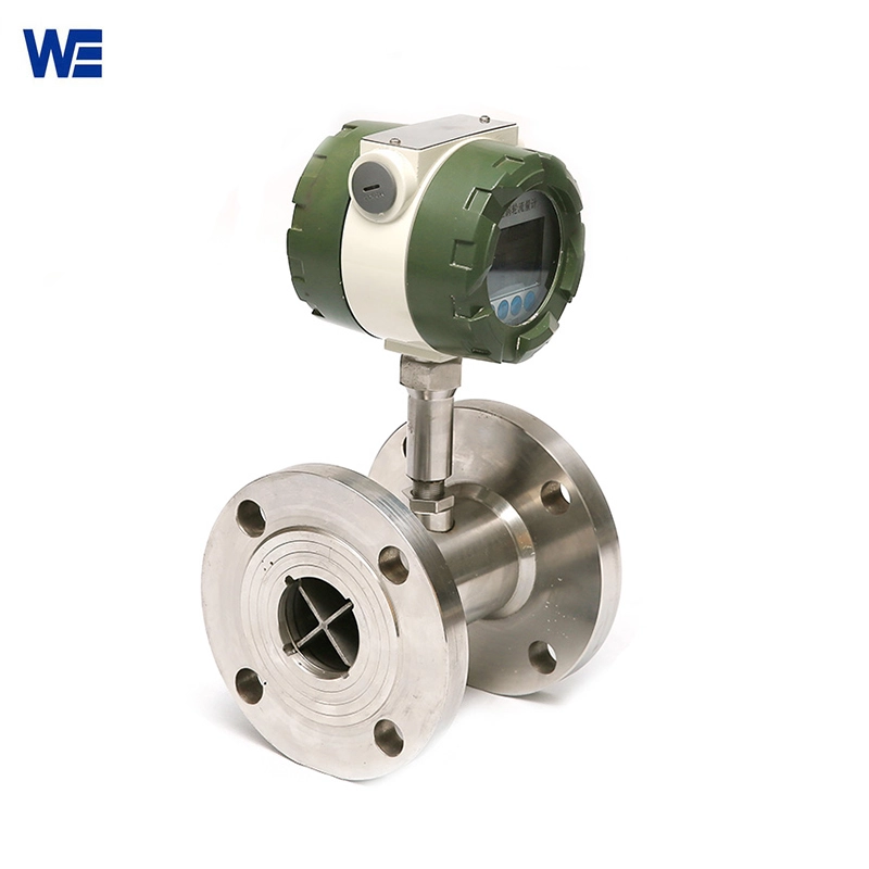
Turbine flow meters react strongly to shifts in fluid thickness. The fluid moves past the meter. It makes the inside rotor turn. The turning speed ties right to the flow amount. But changes in fluid thickness can change the rotor’s speed and the signal it sends out. Thick fluids might slow the rotor down. This leads to readings that are too low. Thin fluids can cause readings that are too high if the meter isn’t set up right.
To keep readings steady, you need to pick a turbine meter that fits the fluid kind. That means selecting suitable rotor and bearing parts that deal with the needed thickness level. Plus, temperature changes that tweak thickness should factor into your system plan. This is especially true for fluids that react a lot to heat.
Fluid Temperature and Pressure: -20°C to +110°C — shifts in this range can still harm accuracy.
Straight Pipe Requirements Before and After the Meter
Flow issues before or after a turbine flow meter can mess up the speed pattern. This brings wrong measurements.
- Upstream: allow a minimum straight pipe length at least 10 times the internal diameter of the pipe.
- Downstream: allow a minimum straight pipe length at least 5 times the internal diameter of the pipe. These short distances help steady the flow before it hits the rotor.
If space limits stop you from having perfect pipe stretches, flow straighteners can cut down on rough spots. Also, keep valves, turns, or pumps away from the meter. They create swirls and whirls that harm accuracy.
Role of Anti-Interference Cables in Signal Stability
Digital turbine flow meters create pulse signals. These signals can pick up electrical noise from around them. Shielded cables stop electrical noise from messing with pulse signals. Good grounding — which people often forget — matters a ton. It boosts signal strength and cuts down on extra sounds. This is key in factory settings with lots of high-power gear. To protect signal quality more, route cables far from high-voltage wires. This lessens outside problems.
2)Calibration Practices for Enhanced Measurement Accuracy
Procedures Involved in Turbine Type Flow Meter Calibration
Calibration begins by checking the turbine meter’s output against a trusted benchmark in steady settings. You test flow amounts at several spots. This checks straightness and repeat results. The info from that helps make fix-up numbers or setup factors. These adjust the meter’s answer pattern.
Newer types, like those from Wepower — an experienced turbine flow meter manufacturer providing industrial process automation sensors — let users enter these factors through a digital setup. This allows on-the-spot fixes.
Frequency and Standards for Calibration Maintenance
For the best outcomes, check the meter at least 1 time per year. But how often you use it, how harsh the fluid is, and how vital the system is might call for more checks. Following ISO/IEC or country measurement rules ensures links back to basics. It also keeps the needed closeness levels.
Regular checks also spot small problems like sensor shifts or part breakdowns — so you can fix them soon.
Comparing Field Calibration with Laboratory Calibration
Field checks are handy for fast looks. But they miss steady surroundings. Lab checks give better exactness. That’s because they use tight flow setups and proven gear. For big-deal uses — like mixing in chemical factories — lab checks are a smart spend.
3)Installation and Operational Considerations for Accurate Measurement
Proper Orientation and Mounting of the Turbine Meter
Turbine meters work in one way only. Turbine type flow meters are designed to measure flow in only one direction. The direction is indicated by the arrow on the body. Wrong setup not only hurts reading exactness but might harm inside parts as time goes on. Also, no shaking during setup is vital — shaky spots can add machine noise to signal handling.
Influence of Control Valves and Flow Controllers on Readings
Put control valves always after the meter. If you place them before, it causes pressure drops. These change fluid speed and weight before the check. In the same way, set flow controllers to cut down on pulses. Since pulses that hit rotor action can make output jumpy.
4)Environmental and Mechanical Factors Affecting Performance
Effects of Temperature, Pressure, and Corrosion on Accuracy
Very hot or cold spots can change material traits or shift sensor starts. Extreme temperatures may alter material properties and sensor performance. On top of that, pressure changes affect fluid weight — which tweaks volume readings.
Harsh liquids bring another risk: corrosive fluids may degrade internal components, leading to measurement drift. Wepower Electronic’s turbine meters come in corrosion-resistant materials like 316 stainless steel or CD4Mcu alloy to combat this.
Routine Maintenance for Long-Term Accuracy Retention
The rotor’s condition is key to how a turbine meter runs. Check rotor blades now and then for damage or junk buildup. That’s a must. Also, cleaning steps stop clogs that might block flow or change how it moves. Even tiny marks on rotors can cause clear error amounts.
5)Common Sources of Error in Turbine Flow Meter Measurements
Mechanical Wear and Rotor Degradation Over Time
Steady use wears down bearings and rods. This cuts turning power and makes weaker pulse signals. It’s a gradual drop — usually missed until big changes show.
Signal Processing Errors Due to Electrical Noise or Faulty Components
Power noise or busted pickup parts can cause jumpy readings. Faulty pickups or damaged wiring can result in erratic pulse generation. Spending on protected wires and checking signal strength at start helps fight this.
Installation Errors Impacting Flow Profile Stability
Wrong pipe size or bad lining during setup causes swirling flows. These twist speed patterns. Installed too close to fittings. Install correctly is a common corrective advice found during troubleshooting.
6)Benefits of Accurate Measurement in Industrial Applications
Enhancing Process Efficiency Through Reliable Data
Exact flow numbers let you tune control valves better. They also make process chains steadier. This brings quicker replies and less power waste.
Improving Product Quality by Maintaining Consistent Flow Rates
In jobs like adding or mixing, even small flow changes can spoil batch evenness. Precise turbine flow meters make sure you control these key tasks tightly.
Reducing Operational Costs Through Preventive Maintenance
By spotting odd things early with steady watching and checks, places skip pricey stops or lost goods — making exactness into real savings.
FAQ
Q1: Can I install a control valve before my turbine meter?
No. It should be installed downstream to prevent pressure disturbances upstream.
Q2: What does it mean if my meter shows fluctuating values?
Possible causes include electrical noise, mechanical wear, or unstable flow conditions.
Q3: Can I use turbine meters with high-viscosity fluids?
It’s best to avoid this, for high-viscosity liquids, we recommend installing the oval gear flow meter.


