- Have any questions?
- +86 15953537010
- admin@wepower-electronic.com

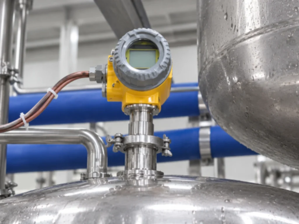
Viscosity often decides whether a product pumps, mixes, coats, or cures as expected. Heavy oil and resin can change enough to upset a batch. Paint and molten polymer can do the same. A water-service sensor will struggle.
The key consideration is whether the viscometer is capable of measuring the medium’s viscosity accurately under real operating temperature and flow conditions and generating a valid output signal.
What Is a High-Viscosity Liquid?
High-viscosity liquids resist movement. Cold gear oil may barely pour, while the same oil flows after heating. Honey and bitumen behave similarly. So do adhesives and chocolate. Dynamic viscosity is stated in mPa·s or cP. Kinematic viscosity in cSt also considers density.
The data-sheet number is only a starting point. Temperature and shear rate can shift viscosity dramatically. A polymer melt may thin while a pump runs and thicken in a quiet pipe. The range should cover normal operation plus credible upsets. A sensor at its limit may respond slowly.
Step 1—Define the Fluid and Measurement Conditions
Gather production data rather than relying on a room-temperature laboratory sample.
Identify the Viscosity Range
Record the minimum and maximum viscosity as well as the normal operating value. A resin line may run at 8,000 cP after heating but reach 30,000 cP during a heater fault. Leave headroom without making normal changes disappear.
Check Temperature Effects
Most high-viscosity liquids thin as they warm. Capture temperatures during start-up and production. Check cleaning and shutdown conditions too. Include heat-tracing variation. Compensation separates formulation changes from thermal shifts.
Evaluate Fluid Composition
Check for solids and fibers. Watch for bubbles, crystals, corrosive chemicals and abrasive particles that may coat or damage the sensing element. Confirm whether the liquid is Newtonian. Non-Newtonian fluids respond to shear, so bypass and line readings may differ.
Step 2—Choose the Right Viscosity Measurement Technology
Fluid behavior determines which measurement principle is credible. A laboratory result cannot correct a blending error in progress.
In-Line Versus Laboratory Measurement
Laboratory viscometers provide controlled tests, but sampling adds delay. An in-line process viscometer lets the control system adjust heating or dosing before an off-spec batch grows.
Common Sensor Technologies
Rotational sensors infer viscosity from spindle torque. Capillary systems calculate it from pressure drop through a narrow tube. Vibrational or tuning fork meters observe a driven element in the liquid. Differential-pressure and ultrasonic designs suit specific arrangements.
Each method has limits. Rotational devices have moving parts. Capillary systems need a predictable flow path. Vibrational sensors need correct immersion. Review the process before choosing.
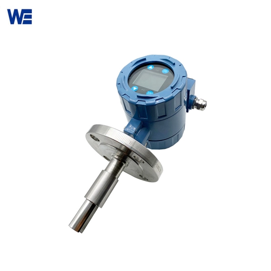
Why Tuning Fork Viscosity Sensors Can Suit Industrial Processes
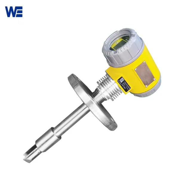
A tuning fork sensor vibrates at a controlled frequency. The liquid changes its damping and energy response. Electronics convert that response into a viscosity value or control signal. There is no rotating spindle in the stream.
This design suits continuous monitoring. It is compact and responds quickly in automated loops. A tuning fork viscosity meter fits lines that need a persistent signal. Hardened product around the fork will defeat any principle.
Step 3—Verify the Sensor’s Technical Specifications
Compare the specification sheet with process data. Check range, accuracy, repeatability, and resolution. Review response time plus temperature and pressure ratings. Confirm that wetted materials suit the liquid and cleaning chemicals.
Process connection, enclosure rating, power supply, and calibration affect commissioning. A 4–20 mA output may suit a basic loop. HART or Modbus adds diagnostics. Ensure the device exchanges data with the plant control system.
Step 4—Consider Installation and Process Design
Installation can create more error than the sensing element. Set insertion depth so the probe is wetted without touching the pipe wall. Avoid dead legs and trapped air. Confirm flow velocity.
High-viscosity service often needs heated pipework or heat tracing. An undersized pump can leave stagnant zones. A bypass loop simplifies isolation and cleaning. Provide pipe size and flow rate plus the temperature profile before finalizing the connection.
Step 5—Assess Maintenance, Cleaning, and Calibration Needs
Sticky liquids coat probes. Pigments and fillers can form a film that shifts readings. Ask how often the element needs cleaning and whether it can be removed with the line isolated. Check for on-site verification.
Total cost of ownership favors a robust sensor with few moving parts, stable electronics, spares, and support. A low price loses appeal when cleaning stops production.
Step 6—Match the Sensor to the Application
Application details narrow the choice. Heavy oil and fuel need broad range plus temperature compensation. Corrosion-resistant wetted materials may be essential. Resins and adhesives benefit from deposit resistance. Food products require hygienic materials and sanitary connections.
Paints and coatings may contain solids or change under shear. Chemical liquids demand compatibility with the product and wash cycle. Polymer processing may require high-temperature capability and fast response. There is no universal viscosity sensor.
A Practical Checklist Before Ordering a Viscosity Sensor
- What about the viscosity range and actual viscosity value?
- Please specify the temperatures during start-up, production, cleaning and shutdown.
- Are solids, bubbles, crystals, or corrosive chemicals present?
- Is continuous in-line measurement required?
- Which process connection and insertion length are available?
- Does the control system need 4–20 mA, HART, Modbus, or another output?
- How will the sensing element be cleaned and calibrated?
- Are hygiene, hazardous-area, or other certifications required?
Conclusion: Select a Sensor for Reliable Process Control
Wepower Electronic supplies industrial viscosity and density measurement solutions for process work. Reliable high-viscosity measurement starts with real process conditions. Define range and temperature. Understand shear and contamination. Check technology, installation, signals, and maintenance together.
Wepower Electronic’s online viscosity measurement solutions can be matched to the liquid and control architecture. Send fluid type, viscosity range, temperature, pressure, pipe size, and required output through the industrial automation instruments team.
FAQ
Q: What viscosity range can a high-viscosity sensor measure?
The usable range depends on the sensing technology and process temperature. Specify the full operating and upset range instead of a single typical value, then leave practical headroom above the maximum.
Q: Are tuning fork viscosity meters suitable for non-Newtonian liquids?
They can be suitable when the installation produces a consistent and representative shear condition. Readings should be validated against the plant’s laboratory method at actual process temperatures.
Q: Does temperature compensation matter for thick liquids?
Yes. Small temperature changes can create large viscosity changes. Compensation or a paired temperature measurement helps distinguish thermal effects from formulation or process changes.
Q: How should a inline viscosity meter be installed in a pipe?
The sensing element must be fully submerged, positioned clear of pipe walls, dead zones and trapped air pockets. Sufficient flow shall be maintained to continuously renew the medium surrounding the sensing element. A bypass loop can simplify isolation and cleaning.
Q: What information should be sent for a sensor recommendation?
Provide specific fluid, viscosity range, temperature and pressure limits, flow conditions, pipe size and density. These details allow a supplier to assess compatibility before quoting.