- Have any questions?
- +86 15953537010
- admin@wepower-electronic.com

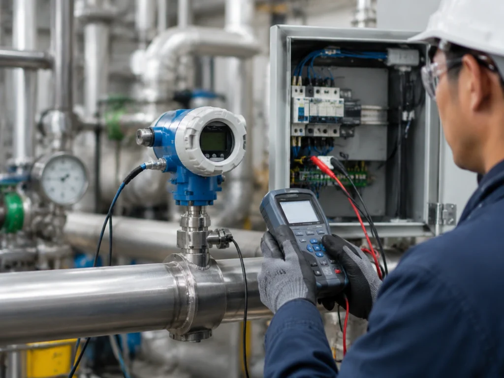
The choice between an RTD and a thermocouple isn’t just about cost; it’s about matching the physics of the sensor to the reality of the plant floor. While RTDs are the go-to for precision, the thermocouple remains the undisputed king of harsh, high heat environments.
Selecting the right sensor requires a look at how they actually perceive heat. They aren’t just different probes; they are different electrical phenomena altogether.
Differences Between RTD and Thermocouple Technologies
A resistance temperature detector (RTD) works by utilizing the predictable change in the resistance of a metal (usually platinum) with temperature. We are measuring the resistance, which rises linearly with the metal’s temperature.
Meanwhile, thermocouples operate based on the Seebeck effect: a tiny voltage is produced at the joint of two different metals. Unlike active measuring devices, thermocouples work passively — the temperature difference alone generates the millivolt-level electrical signal. These distinct physical properties dictate how each sensor handles environmental stress and signal stability. An RTD needs an external excitation current, which introduces the risk of self heating, whereas a thermocouple is essentially its own power source.
When Does a Thermocouple Temperature Transmitter Become the Necessary Choice?
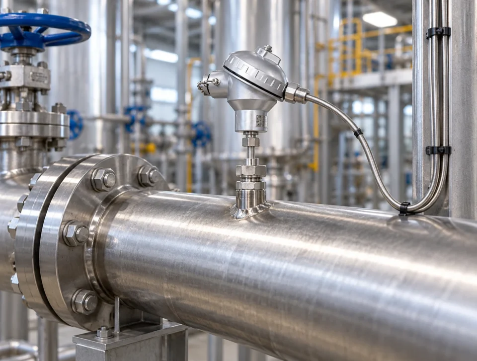
Sometimes an RTD just won’t get it through the week. The thermocouple is typically the only practical option if the process is burning red or rattling the bolts free. With integrated assemblies that can withstand temperatures of up to 1000°C or more, thermocouples perform exceptionally well in hot conditions.
Platinum RTDs are prone to mechanical damage and measurement deviation under prolonged high-temperature operating conditions. The glass or ceramic insulators in an RTD begin to degrade or become marginally conductive after you above that 600°C threshold, which destroys the readout.
The Case for RTDs: Prioritizing Precision and Long Term Stability
Where process temperatures remain mild, generally not exceeding 400°C, resistance temperature detectors outperform alternative sensing devices.
RTDs provide superior linearity and repeatability compared to thermocouples. A thermocouple’s signal can be “messy” and non-linear, requiring complex compensation. Applications in chemical processing often demand the tight tolerances that only a Pt1000 or Pt100 sensor can provide. Signal drift over time is significantly lower in RTD systems, reducing the frequency of required calibrations. In a pharmaceutical batch, a two degree drift could mean a lost product; in that world, the stability of platinum is worth every penny.
How Integrated Transmitters Solve Common Signal Interference Issues
A raw sensor signal is a weak thing. Whether it’s a few ohms of resistance or a handful of millivolts, it doesn’t travel well across a factory floor filled with motors and VFDs.
Why Convert to a 4–20 mA Signal at the Measurement Point?
Long distance cable runs are susceptible to electromagnetic interference (EMI) and radio frequency interference (RFI). If you run a thermocouple wire past a large motor, the induction can easily add a few degrees of “ghost” temperature.
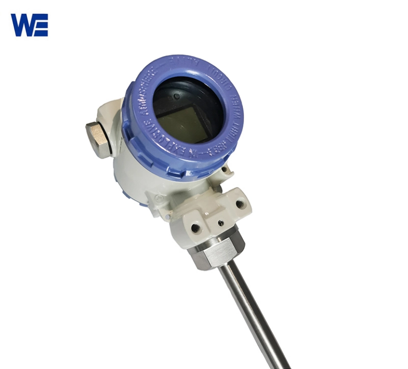
Integrated transmitters convert low level millivolt or resistance signals into a robust 4–20 mA current loop. This current loop is much harder to distort. Moreover, the 4–20 mA signal format negates the use of pricey dedicated extension cables, lowering total installation outlay. You can use standard twisted pair copper instead of pricey compensated thermocouple wire.
Enhancing Data Integrity for DCS and Scanners
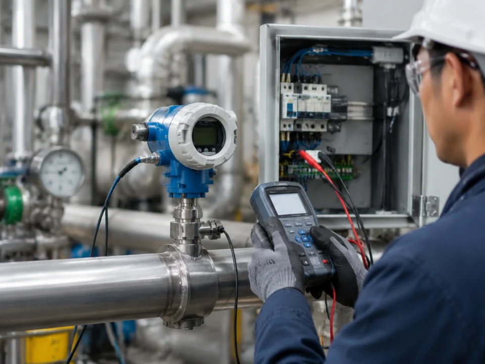
Digital signal conditioning ensures that the temperature data arriving at the control room is an accurate reflection of the field conditions. A thermocouple temperature transmitter can linearize the signal and perform cold junction compensation right at the source. Modern transmitters allow for direct input into computers and recording devices without additional signal converters. This “clean” data stream makes the life of a DCS programmer much easier, as the scaling is handled before the signal even hits the I/O card.
Choosing the Right Housing and Display for Your Field Environment
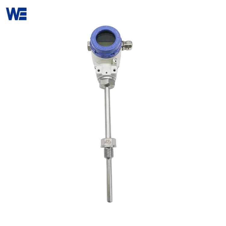
The “transmitter” part of the equation also involves the physical box it sits in. You need to decide how much information you need at the point of measurement.
Local LCD vs. LED Displays
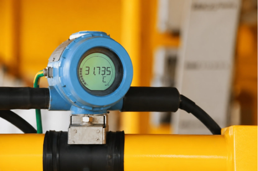
Local displays allow field technicians to verify process temperatures without communicating with the control room. This is a massive time saver during commissioning.
- LED displays offer high visibility in lowlight indoor plants, glowing brightly even through a layer of dust. Meanwhile,
- LCDs are often preferred for outdoor sunlight readability where an LED would be washed out.
Basic aluminum alloy housings without displays provide a cost effective, rugged solution for remote or inaccessible locations where no one is around to look at a screen anyway.
Application Specific Selection: Where Should You Deploy Each?
General rules are fine, but specific industries have their own “standard” for a reason.
Oil, Gas, and Petrochemical Requirements
These industries commonly opt for integrated thermocouple units thanks to their resistance to erratic thermal conditions and high-pressure working surroundings.
.When dealing with flare stacks or crude heaters, the temperatures are simply too high for RTDs. Protection tubes and thermowells must be matched to the corrosive nature of the fluid or gas being measured. Often, these are heavy walled Inconel or Hastelloy wells that house a Type N or Type K thermocouple.
Pulp, Paper, and Machinery Measurement
RTDs are frequently selected for these industries due to the moderate temperature ranges and the need for high precision in drying and chemical treatment phases. In a paper mill, keeping the rollers at a exact temperature is key to paper quality. Small scale integrated transmitters allow for easy mounting on compact machinery and tanks, providing a 4-20mA signal directly to the PLC without taking up much space.
Key Questions to Ask Before Finalizing Your Specification
Before you sign off on a purchase order, run through this mental checklist:
- What is the maximum continuous operating temperature of the process? (If >600°C, go thermocouple).
- Is the installation point subject to significant mechanical vibration or thermal shock? (If yes, thermocouple is safer).
- Does the control system require a 4–20 mA signal or a direct digital interface? (Transmitters are non-negotiable here).
- Is a local visual readout necessary for safety or maintenance protocols? (Choose your housing accordingly).
Contact Wepower Electronic today to discuss your temperature measurement requirements and find a transmitter solution built for your plant floor.
FAQ
Q: Can I use a thermocouple transmitter with an RTD sensor?
No. The electronics are fundamentally different. A thermocouple temperature transmitter looks for millivolts and performs cold junction compensation, while an RTD transmitter measures resistance. Some “universal” transmitters can be reconfigured for both, but you must check the manual.
Q: Does wire length matter for 4-20mA transmitters?
Within reason, no. Because it is a current loop, the transmitter will adjust its voltage to maintain the correct current regardless of the wire resistance (up to the limit of the power supply). This is why transmitters are preferred over direct wiring sensors to a PLC.